")
")
1. Title and functionality.
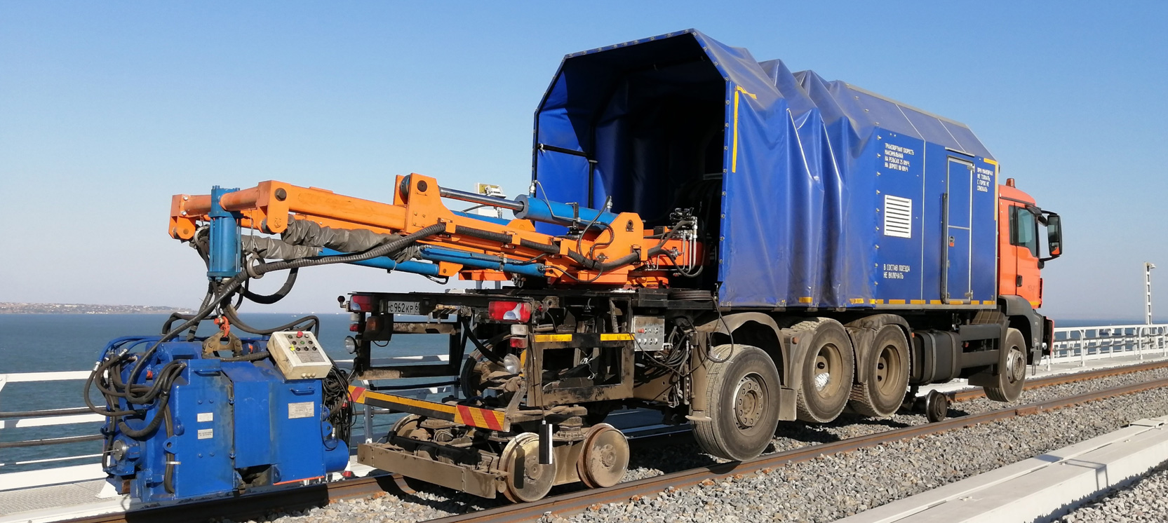
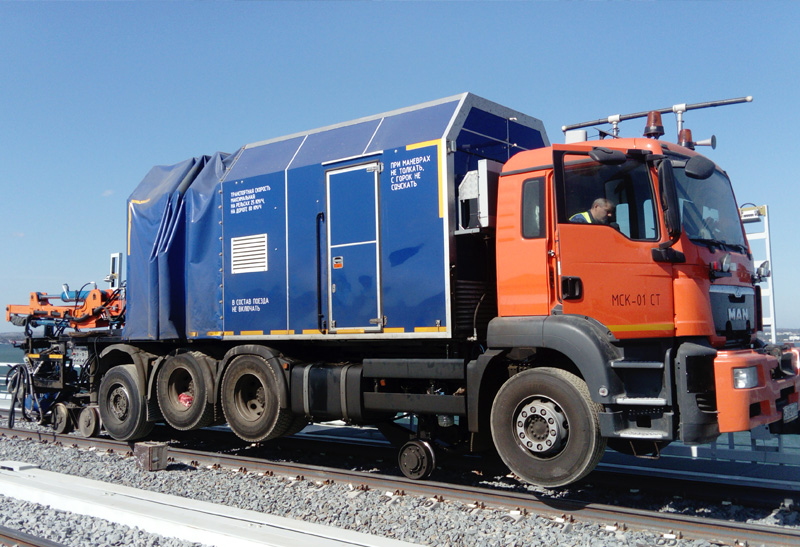
1.1. The MSK-01 ST road-rail truck-based rail-welding system (hereinafter referred to as the “MSK-01ST system”) is used for the flash butt welding of rails directly in-track by way of continuous or pulsatile flashing. The MSK-01 ST system can operate both on rail track and a conventional road. It is used for rail-welding during the maintenance of the existing rail tracks and for the construction of new tracks.
Rail cross section from 6,500 mm2 to 10,000 mm2. Deburring is performed immediately after welding.
MSK-01 ST road-rail truck-based rail-welding system operating conditions: Temperature range: -10°С to +40°С; Max. ambient humidity: 80% at +20°С and up to 100% at + 25°С
2. Technical specifications.
2.1. The MSK-01 ST road-rail truck-based rail-welding system includes a truck chassis with bogies (adapters), a housing for the installation of the equipment including a hydraulic manipulator, a suspended rail-welding machine, an induction heating machine for post-weld heat treatment, and a set of grinders for welded joints machining.
2.2. The MSK-01 ST system includes:
- Truck chassis with outrigger jacks;
- Housing;
- Hydraulic manipulator;
- Suspended flash butt rail-welding machine MSR-120.02 U1 with a control system and closed loop cooling system;
- Induction heating machine UIN 001-100/RT-P for post-weld heat treatment;
- PTO-driven genset;
- Electric hoists for the lifting and loading of production equipment;
- Equipment for abrasive machining of welded joints;
- Spare parts kit.
2.1.1. Base truck chassis
- Truck chassis manufacturer: MAN
- Engine: MAN D2676LF0 (may be changed)
- Engine capacity: 12.4 L
- Fuel: diesel
- Number of axles: 4
- Max. permissible weight (with container): 32,000 kg
- The vehicle is equipped with front and rear bogies (railway adapters) to enable movement on rail track. The rear bogie is driven by hydraulic drive motors. The front bogie is idle.
- Railway gauge: 1520 mm or 1435 mm
- The outrigger jacks located at the rear of the vehicle are used to ensure stability during operations.
- The vehicle is equipped with rigid tow bars on both ends for attachment to a railroad vehicle for emergency towing.
- Rotating beacons are installed on the truck cab.
2.2.2. Housing design.
The housing is used for the installation of the entire system equipment to ensure its safe operation and protection against environmental exposure.
The equipment compartment is separated from the manipulator and welding compartment.
The base of the housing is an enhanced and reinforced truck chassis frame. The roof and walls are made of sandwich panels. The interior paneling of the walls is made of shaped aluminum sheets. The floor is made of shaped steel sheets. The housing is equipped with side doors with rubber gaskets to ensure fast access to the installed equipment. The doors are equipped with locks. The manipulator compartment is equipped with a sliding tent on a folding metal frame.
The housing has 24 V primary lighting, 24 V emergency lighting, and 220 V exterior lighting of the working area. The housing is equipped with three-phase and single-phase 220 V electrical receptacles for powering electric tools.
The housing is equipped with dry powder and carbon dioxide fire extinguishers (4 pcs).
2.2.3. Hydraulic manipulator.
The hydraulic manipulator is used for the smooth positioning of the welding head on the rail joint. The manipulator is operated using controls located on the right and left sides of the manipulator as well as directly on the welding head.
The hydraulic manipulator specifications are shown in Table 1 below.
Table 1
Parameter |
Value |
|
Manipulator capacity, kg |
4000 |
|
Boom operating radius, mm |
4000 |
|
Welding head lifting height from track surface, mm |
550 |
|
Rotary travel, deg. |
± 60 |
|
Hydraulic oil pressure, MPa |
21 |
|
DC voltage, V |
24 |
Manipulator hydraulic cylinder rods are protected with weld spatter resistant housings.
In case of power interruption, the manipulator stops automatically if its operating elements are not in a zero position. It is also possible to manually raise, lower, and retract the boom into a safe position.
2.2.4. Specifications of the MSR-120.02.U1 welding machine with control system and closed loop cooling system. Machine specifications and dimensions are listed in Table 2 below.
Table 2
Parameter |
Value |
|
Operating supply voltage, V |
380 |
|
Supply frequency, Hz |
50 |
|
Apparent power at 50% duty cycle, kVA min. |
240* |
|
Max. secondary current, kA min. |
72 |
|
Sustained secondary current, kA |
21,4* |
|
Secondary circuit impedance, μOhm, max |
110 |
|
Welding transformers ratio |
48 |
|
Max upset force, kN |
1 500 |
|
Nominal upset force at 30.0 MPa, kN |
1 200 |
|
Max gripping pressure, kP |
3 200 |
|
Gripping pressure at 29.0 MPa, kP |
2 800 |
|
Hydraulic system operating pressure, in the upset line with tightening, MPa (kgf / mm(кгс/мм |
30,0 (300) |
|
Hydraulic system operating pressure, in the gripping line with tightening, MPa (kgf / mm |
29,0 (290) |
|
Max upset speed, mm / s, min. |
30 |
|
Burn-off speed adjustment range, mm/sec |
0,2-1,2 |
|
Movable housing travel, mm |
95 |
|
Max. welding time for R-65 rail, sec |
240 |
|
R-65 rail min. welding performance, welds/hour |
8 |
|
Dimensions, mm (length x width x height): |
1 876х993х1 130 |
|
Weight, kg |
3 750 |
After welding, the machine performs automatic deburring with the subsequent return of the equipment into the initial position.
The control system is built using the Omron NX series industrial controller and ensures the following:
- Set up, adjustment, and monitoring of the quality-relevant process parameters of the welded joints
- Welding process control
- Actuators status monitoring
- Power system status monitoring
- Real-time updates on the welding process progress
- Registration and storage of welding process data for each welded joint
- Issue of certificates for each welded joint
- Self-monitoring and diagnostics
The control system automatically compares the actual and target parameters and visualizes the welding process status using diagrams and tables.
Each welded joint certificate (welding report) contains the following information:
- Operator name
- Foreman name
- Welding date
- Joint number
- Rail type
- Welding conditions
- Welding duration
- Welding process oscilloscope record
- Primary welded joint conformance data based on the tolerancing results
Closed loop self-contained cooling system ensures the reliable and efficient heat removal from the welding machine electrodes and transformers. Coolant – G12 antifreeze or similar.
2.2.5. Induction heating machine UIN001-100/RT-P for post-weld heat treatment.
High frequency induction heating machine UIN 001-100/RT-P is used for post-weld heat treatment directly in track. Post-weld heat treatment is performed by the uniform heating of the entire rail cross-section in the welded joint area to a specified temperature with subsequent rail head hardening by forced cooling with compressed air.
Machine components:
- Frequency converter
- Heat treatment unit consisting of a heater, a hardening device and a heat treatment control unit.
- Compressor with receiver
- Water cooling unit
- Switching units
The UIN 001-100/RT-P machine specifications are listed in the Table 3.
Table 3
Parameter |
Value |
|
Conversion frequency, kHz |
8 |
|
Heating temperature, °С |
850÷900 |
|
Heating time, s, max. |
240 |
|
Colling time, s, min. |
180 |
|
Frequency converter cooling |
water-cooled |
|
Inductor cooling |
water-cooled |
|
Cooling system pump capacity, l/min, min.. |
6 |
|
Coolant pressure, MPa, min. |
0,2 |
|
Air-supply system operating pressure, MPa |
0,5÷0,8 |
|
Air flow rate, l/min, min. |
4000 |
|
Overall dimensions of components, mm, max. (length x width x height) |
|
|
Chiller |
710×563×1626 |
|
Thermomodule |
841×502×670 |
|
Frequency converter |
559×530×1040 |
|
Compressor |
1240×800×1280 |
|
Receiver |
1200×620×620 |
|
Weight of components, kg, max. |
|
|
Chiller |
220 |
|
Thermomodule |
50 |
|
Frequency converter |
120 |
|
Compressor |
530 |
|
Receiver |
100 |
Heat treatment mode for welded joints of R65 type rails (for reference).
Heating:
- power consumption 25-75 kVA;
- heating temperature 850-900 °C;
- conversion frequency 8-15 kHz;
- pause after heating 12±3 s;
- heating time, max. 180-245 s.
Cooling (head hardening):
- cooling time, min. 180 s;
- operating air pressure 0.5-0.8 MPa;
- air flow rate, min. 3600 l/min.
The heat treatment process control unit provides fully automated process with minimal operator involvement and implements the following functions:
- heat treatment parameters setting and monitoring (heating temperature, heating time, frequency converter power, hardening time, hardening unit air pressure);
- System equipment tech status monitoring based on signals from sensors and limit switches;
- heating treatment tech process visualization;
- data certificate creation, accumulation and storage (information about the process of the heat treatment) for each welded joint with the possibility of printing them on the built-in printer;
- shift report based on the results of the System shift work creation with the issuance of a report for each joint (valid / invalid) with the possibility of printing them on the built-in printer at the end of the shift.
To provide the required air flow a compressor with a capacity of at least 3,600 l/min (at 8 bar) with a 250-liter receiver is used.
2.2.6. PTO-driven genset
The genset specifications are shown in Table 4 below.
Table 4
Parameter |
Value |
|
Truck engine type |
Turbocharged diesel |
|
Engine electronic control |
Common Rail |
|
Truck engine model |
D2676LF* |
|
Number of cylinders |
Straight-six |
|
Engine capacity, L |
12,4 |
|
Prime Power at 1800 rpm, kW |
397 |
|
Specific fuel consumption, L/kWh |
0,188 |
|
Fuel tank capacity, L |
500 |
|
Cooling system |
Liquid coolant |
|
Alternator |
Stamford HCI 434F2* |
|
Power at 1500 rpm, kVA |
400 |
|
Frequency, Hz |
50 |
|
Diesel engine speed compensator |
Electronic |
* The Manufacturer reserves the right to make any changes to the design and configuration of the system at any time without prior notice as long as such changes do not impair the system specifications.
2.2.7. Electric hoist for lifting the load into the MSK-01ST system.
Stationary electric hoist type RA is used for lifting, holding, and lowering loads as well as for moving loads horizontally.
Table 5
Parameter |
Standard value |
|
Operating voltage, V/Frequency, Hz |
220/50 |
|
Lifting capacity, kg |
250 |
|
Lifting height, m |
6 |
|
Lifting speed, m/min |
8 |
|
Engine power, kW |
0,9 |
|
Dimensions LxWxH, mm |
370х120х220 |
|
Weight, kg |
16,5 |
2.2.8. Manual grinding and rail cutting tools.
3. MSK-01ST road-rail truck-based rail-welding system includes:
- Base truck chassis
- Railway bogies (adapters)
- Housing
- Hydraulic manipulator
- MSR-120.02U1 welding head with a control system and closed loop cooling system
- Alternator
- High frequency induction heating machine UIN 001-100/RT-P;
- Spare parts kit for the warranty period;
- Operating documentation.
* The Manufacturer reserves the right to make any changes to the design and configuration of the system at any time without prior notice as long as such changes do not impair the system specifications.
4. Safety requirements.
4.1 Climatic design TZ, location category 1 (according to GOST 15150).
4.2. Safety requirements for the components of the MSK-01ST system are listed in the respective component operating manuals.
4.3. Protection class of energized components of the MSK-01S system is IP 20 (except for welding machine electrodes, which is IP 00) according to GOST 14254-96.
4.4. The MSK-01ST system electric shock protection class - 01 according to GOST 12.2.007.0-75.
5. Acceptance procedures.
5.1. The MSK-01ST system acceptance procedures are carried out by the Customer’s representatives at the Manufacturer’s facility.
6. Delivery Terms and Conditions.
6.1. The delivery Terms and Conditions for the MSK-01 ST road-rail truck-based rail-welding system is carried out on the terms of EXW Pskov Russia according to INCOTERMS-2010.
7. Delivery time.
7.1. Delivery time for the MSK-01 ST road-rail truck-based rail-welding system is 12 months.
8. Pre-commissioning works.
8.1. The Manufacturer performs the start-up and pre-commissioning works for the MSK-01 ST road-rail truck-based rail-welding system at the Customer's facility.
9. Training.
9.1. The Manufacturer performs the training of the Customer’s personnel on the operation and maintenance of the MSK-01 ST system.
10. Warranty.
10.1.The warranty period for the MSK-01 ST road-rail truck-based rail-welding system is twelve months after the commissioning date.
11. Post-warranty service and maintenance.
11.1. Upon the expiration of the warranty period, the Manufacturer, if agreed with the Customer, can provide post-warranty service and carry out the maintenance of the MSK-01 ST road-rail truck-based rail-welding system, including maintenance schedules and supply of the required spare parts.
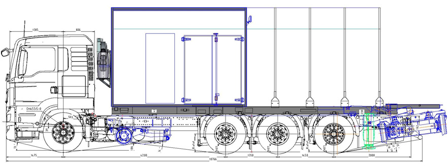
Layout diagram of the MSK-01 ST road-rail truck-based rail-welding system
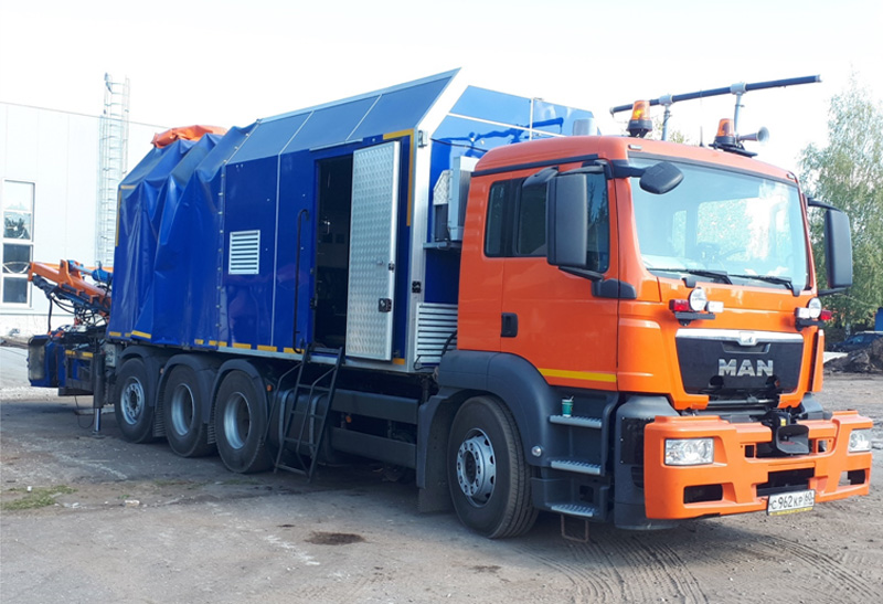
MSK-01 ST System General appearance
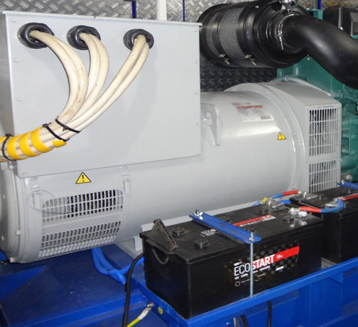
Stamford electric generator
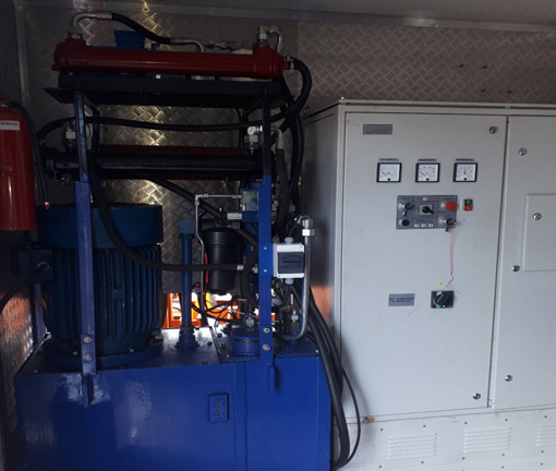
Hydraulic power unit
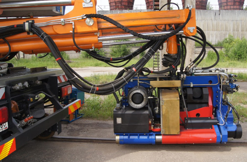
Hydraulic manipulator with rail-welding machine
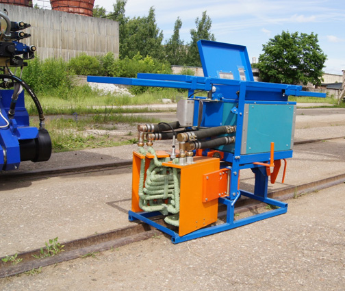
Induction heating unit